Skateboard Trick Tracker
A Covid-19 affected senior project
By Neal Crawford
Background
Every sport is fueled by a desire to improve.
In skateboarding this desire is found in the weeks nailing down a new trick,
and the months spent trying to land it with consistency. The ability to track this improvement is invaluable.
While landing on the pavement with both feet still on board is rewarding in its own sense, seeing the data
behind that progress is solid evidence of how far you've come.
My senior project attempts to accomplish this task. The device comes in the form of a small “trick tracker”
mounted to the bottom of one’s skateboard. It should instantly recognize which tricks the user performed, and report this data to the skater's phone.


Existing Solutions
Googling "skateboard trick tracker" shows prototyped products that never made it to market.
Currently a skater would have to manually tally their trick statistics on a notepad or their phone, rather
than taking advantage of the automatic tracking provided by this device.
The tracking and point system will bring a game-like element to the skateboarding experience.
User Needs
My top goal for this project was to make the device as unobtrusive as possible.
My vision for the product was to be an assistant more than a hassle.
No one wants to be hassled by another tech gadget, or be conscious of any effect it could have
on the skateboard. This condition alone puts several requirements on the trick tracker, which I will rationalize below.
Required is a lightweight device utilizing a small footprint on the board. Anything weighing
over a fraction of the skateboard's weight would noticeable change its movement. The skater
should also not have to worry about the tracker sticking out and potentially hitting the ground during a trick.
Another condition of unobtrusiveness is battery life. This device lasts 8 hours on a single charge,
meaning it will last several sessions before needing a recharge via USB.
Lastly, one of the main features that keeps the trick tracker from slowing one down is its
ability to wirelessly provide its data to the skater's phone.
The full list of user requirements can be found in the following table.
| User Requirement No. |
Requirement: |
|---|---|
| 1 |
The tracker shall be operational for at least two skating sessions |
| 2 | The tracker shall provide real-time feedback to the user |
| 3 |
The tracker shall provide the user with a list of tricks they performed, and a rating for how cleanly the trick was performed |
| 4 | The tracker shall be mounted to any skateboard in a non-instrusive manner |
| 5 | The tracker shall be user rechargable. |
| 6 | The tracker shall be competitively priced as compared to similar devices on the market |
| 7 | The tracker shall store the motion data of the active trick being performed, as well as the total session tally of the amount of times each trick was performed, the rating, and the user's total score |
| 8 | The tracker shall be operational by senior project demo day |

Design
The trick tracker is intended to be a low cost solution. Based off the total cost of components I would market the trick tracker at $99.99, slightly over 3x the cost of manufacture. Component costs would be cheaper in mass production. I believe this is a fair MSRP given the fact that this would be the only device of its kind on the market. Below are the component prices if ordering at a quantity to produce a single board.
| Quantity | Part | Digi-Key Part Number | Unit Price |
|---|---|---|---|
| 14 | RESISTOR | - | 0.10 |
| 17 | CAPACITOR | - | 0.20 |
| 2 | LED GREEN CLEAR SMD | 160-1446-1-ND | 0.26 |
| 1 | CONN HEADER R/A 2POS 1.5MM | 455-1669-ND | 0.19 |
| 1 | CONN RCPT USB2.0 MICRO B SMD R/A | 609-4618-1-ND | 0.43 |
| 1 | SWITCH SLIDE SPDT 300MA 6V | 401-1999-1-ND | 0.56 |
| 1 | SWITCH TACTILE 0.05A 12V | 732-7004-1-ND | 0.49 |
| 1 | MCU 32BIT 512KB FLASH | MK22FN512VLH12-ND | 8.54 |
| 1 | IC CONTRLR LI-ION 4.50V SOT23-5 | MCP73831T-5ACI/OTCT-ND | 0.56 |
| 1 | IC REG LINEAR 3.3V 300MA SOT23-5 | 576-4764-1-ND | 0.11 |
| 1 | BLUETOOTH MODULE BLE CHIP SMD | 150-RN4871-I/RM140-ND | 7.03 |
| 1 | CRYSTAL 8.0000MHZ 18PF SMD | 535-9720-1-ND | 1.09 |
| 1 | 3.7V 2000mAh Battery | N/A | 4.39 |
| 1 | Printed Circuit Board | N/A | 3.17 |
| Total Cost | $31.88 | ||
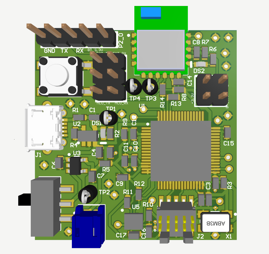
Board dimensions come in at just 1.35" x 1.57" including the bluetooth module. Below is the 3D rendering of my final board design.
Project Timeline
The original timeline for the development of this project was planned prior to beginning hardware and software design.
This fell apart rather early due to the COVID-19 pandemic. Boards fabricated in China were delayed while in-person classes
were cancelled at the same time. With no access to previously available lab equipment, I moved to designing a proof of
concept device utilizing just the K22F development board and its on-board accelerometer.

Technical Details
Full System Requirements
The last step before beginning design was determining what the product does and how, in the form of user and system requirements. From here I could determine the components necessary to make the trick tracker a reality.
| User Requirement No. |
System Requirement No. | Requirement |
|---|---|---|
| 1 | The tracker shall be operational for at least two skating sessions | |
| 1 | The tracker shall last up to 8 hours on a single charge | |
| 2 | The tracker shall provide real-time feedback to the user | |
| 1.1 | The tracker shall communicate wirelessly | |
| 2 | Tracker feedback shall be readable on a computer or phone | |
| 3 | The Tracker shall provide the user with a list of tricks they performed, and a rating for how cleanly the trick was performed | |
| 1.1 | The tracker shall collect pitch/roll/yaw data on the skateboard | |
| 4 | The tracker shall be mounted to any skateboard in a non-instrusive manner | |
| 1 |
The tracker shall be no larger than 2" wide x 1.5" long x 0.75" tall | |
| 2.1 | Tracker shall weigh no more than 5 ounces | |
| 3.1 | The tracker shall be mount/unmountable with several screws on the board | |
| 5 | The tracker shall be user rechargable. | |
| 1 | The tracker shall be USB rechargable | |
| 6 | The tracker shall be competitively priced as compared to similar products on the market | |
| The final tracker design shall cost less than $35 in components | ||
| 7 | The tracker must store the motion data of the active trick being performed, as well as the total session tally of the amount of times each trick was performed, the rating, and the user's total score | |
| 1 | The tracker shall have at least 128KB of RAM | |
| 8 | The tracker shall be operational by senior project demo day | |
| 1 | The tracker shall be operational by June 2020 |
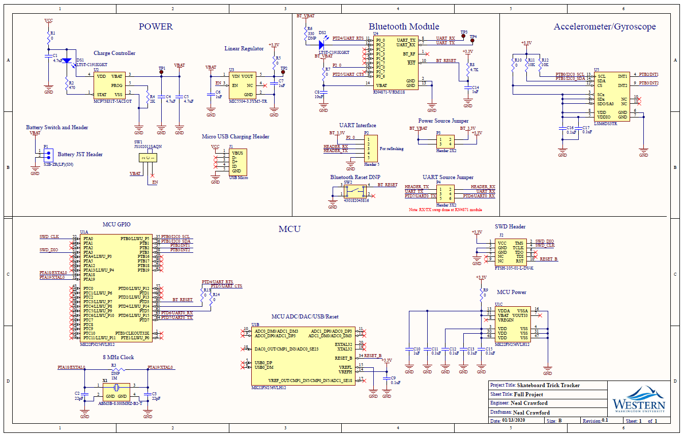
Schematic
After determining the scope of the project and nailing down system requirements, it came time to design a schematic. Schematic capture and PCB layout were done entirely in Altium Designer.
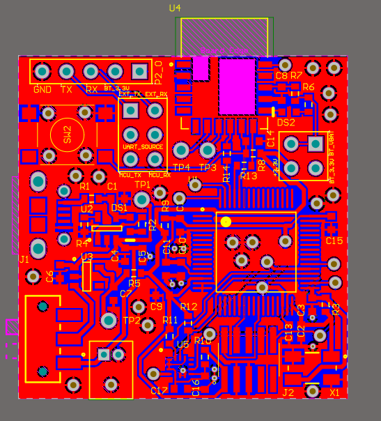
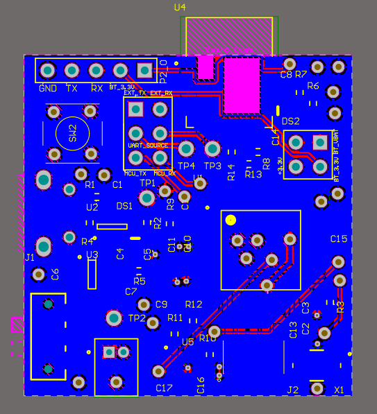
PCB
With the schematic finished, I could start the board layout. This process took the longest because of my size requirements. Just placing the components took many iterations, as I squeezed everything into the smallest possible footprint. Routing each trace using few vias took even longer. The final result was a board measuring 1.35" x 1.41" (34.4 x 35.8mm) without the bluetooth module. The module adds 4mm to the long edge of the board.
Bill of Materials
| Manufacturer | Description | Designator | Value/Part No. | Quantity |
|---|---|---|---|---|
| N/A | Capacitor | C2, C3 | 22pF | 2 |
| C9, C11, C12, C13, C15, C16, C17 | 0.1uF | 7 | ||
| C1, C4, C5 | 4.7uF | 3 | ||
| C6, C7, C10, C14 | 1uF | 4 | ||
| C8 | 10uF | 1 | ||
| LITE ON | 2-Pin SMD LED, Green, 574 nm | DS1, DS2 | LTST-C191KGKT | 2 |
| Amphenol ICC | Micro USB R/A SMTCONNECTOR | J1 | 10118194-0001LF | 1 |
| Samtec Inc. | 10 pos. Surface Mount Header | J2 | FTSH-105-01-L-DV-K | 1 |
| JST Sales America Inc. | 2Pos Female JST Header | P1 | S2B-ZR(LF)(SN) | 1 |
| N/A | Resistor | R1, R5, R7, R9, R10, R13, R14 | 0 Ω | 7 |
| R2 | 200Ω | 1 | ||
| R6 | 330 Ω | 1 | ||
| R4 | 2KΩ | 1 | ||
| R8 | 4.7K Ω | 1 | ||
| R11, R12 | 10KΩ | 2 | ||
| R3 | 1M Ω | 1 | ||
| C&K | Horizontal SMT SlideSwitch JS102011SAQN | SW1 | JS102011SAQN | 1 |
| Würth Elektronik | WS-TASV SMD Tact Switch 6X6 mm | SW2 | 430182043816 | 1 |
| .040"D TESTPOINT | TP1, TP2, TP3, TP4 | Keystone_5001 | 4 | |
| NXP | 120 MHz Cortex-M4 Based Microcontroller | U1 | MK22FN256VLH12 | 1 |
| Microchip Technology | Li-Ion, Li-PolymerCharge Controller, 4.5V, 5-Pin SOT-23 | U2 | MCP73831T-5ACI/OT | 1 |
| Microchip Technology | Single LDO, Fixed Out 3.3 V, 5-Pin SOT-23 | U3 | MIC5504-3.3YM5-TR | 1 |
Microchip Technology |
Bluetooth 4.2 LowEnergy Module, 16-Pin SMD | U4 | RN4871-V/RM118 | 1 |
| STMicroelectronics | Accelerometer and 3D Gyroscope, 14-Pin LGA | U5 | LSM6DS3TR | 1 |
| Abracon LLC | Ceramic SMD Crystal,8 MHz, 4-Pin SMD | X1 | ABM3B-8.000MHZ-B2-T | 1 |
| N/A | Header, 3-Pin, Dual row | UART_SOURCE | HDR2X3 | 1 |
| Header, 5-Pin | P2 | HDR1X5 | 1 | |
| Header, 2-Pin, Dual row | P3 | HDR2X2 | 1 |
Software Design
Full code on GitHub 
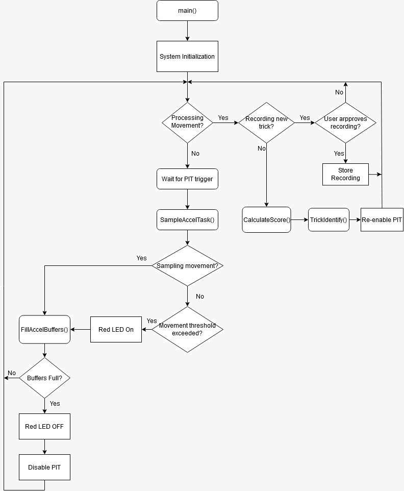
This figure below describes the main event loop of the program. Pressing SW3 on the K22 will begin
recording a new trick for potential storage in the database. The accelerometer is sampled at 800Hz
(every 1.25ms). This is timed using the K22's PIT.
If a threshold of movement is exceeded, the next two seconds of motion data are captured. At the end of
this two second period, if the user was recording a trick for the database, they may confirm by again
pressing SW3. If they don't want the trick saved they may press SW2 and return to the main event loop.
If no trick is being recorded, the system will calculate a "movement score" based off the total movement
of all axes. Next the system will attempt to match the movement data with a trick stored in the database.
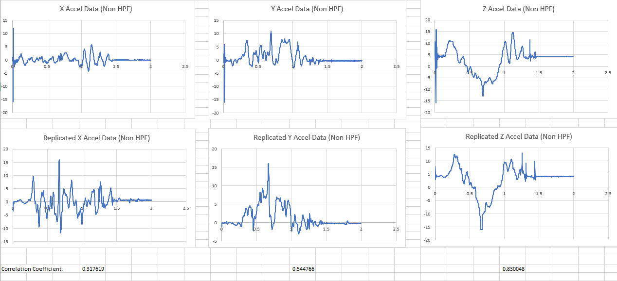
Trick Identification Methodology
Tricks are differentiated from each other using correlation of acceleration data. The correlation coefficient is found using the following formula:
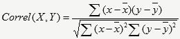
A coefficient is found between a reference set of data points, X, and the results of the currently performed trick, Y. The more similar X and Y, the closer the coefficient to 1. This is evident in the Y and Z plots.
The X plot has the lowest coefficient, since this axis faces the same direction throughout the particular example trick.
X axis data can be treated as random noise in this case.